|
Ban
- SHE
62in EPP
Crash Resistant Sports Aerobatic Slope Soarer
Designed
by Stan Yeo
Produced
by PHOENIX MODEL PRODUCTS
Introduction
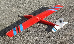
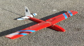
The Ban-SHE
is a stylish high performance 62in (1600mm) span crash resistant aerobatic
EPP slope soarer designed for the modeller wanting to combine EPP durability
with 'rigid' structure performance. It is intended that Ban-SHE is built
with wing mounted aileron servos with the ailerons being used as flapperons
with elevator flap coupling. In this mode Ban-SHE can perform must aerobatic
manoeuvres including outside loops, horizontal eights and sustained inverted
flight etc. If using a non-computerised transmitter the model becomes
a conventional 3 channel aerobatic sloper with the ailerons operated via
'Y' lead. Ban-SHE will fly in most wind conditions depending on the quality
of the lift. Very strong winds may require the model to be ballasted on
the balance point.
As with
all EPP models building time has been kept to a minimum; typically 8 -12
hrs depending on the skill and care taken. Field repairs if required are
of the Elastoplast variety!
Tools
/ Materials Required
The only
tools required are a modelling knife with spare blades, a pair of sharp
scissors, soldering iron 180 grade Wet & Dry sanding block, masking tape,
a can of impact spray adhesive such as Stikatak, some runny super glue
(please observe safety precautions on packets!), epoxy and a soldering
iron.
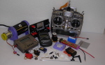
R/C
Equipment
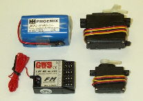
The R/C Equipment
used in the prototypes consisted of two standard size servos (HS300) for
the rudder and elevators, two metal geared micros (HS81MG) for the ailerons,
a standard AA size Rx battery and a 6/8 channel receiver (GWS). All the
items are available from PMP at competitive prices.
Building
the Fuselage
- Lightly sand the fuselage sides, top and bottom with 180 grade wet
and dry to remove the 'release' agent. Remove dust with a small brush
or vacuum cleaner.
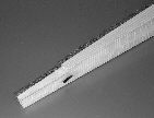
- Drill wing dowel holes in fuselage sides and fit fuselage distance
pieces and nose former to one fuselage side.
- Using thin superglue fit 4.5mm sq. strip, tail post and triangular
nose strip to fuselage. Check you have a left and right side!
- Join fuselage sides together over plan ensuring fuselage is straight.
Cut nose top to length and fit.
- Cut fuselage top to length and glue in position.
- Fit elevator and rudder servos to balsa bearers and determine which
side of servo the elevator pushrod needs to be for the elevator to operate
in the correct sense! Position servos inside fuselage (Do not glue).
- Drill holes for control rods in fuselage sides 120mm forward of the
end of fuselage (see plan). Shamfer side of holes to reduce control
rod exit angles. Keep control rods as straight as possible to avoid
them binding
 Fit control cable outers and attach to fuselage sides using CW Tape
or balsa blocks.
Fit control cable outers and attach to fuselage sides using CW Tape
or balsa blocks.- Do not glue elevator servo in position until after the tailplane
is fitted.
- Fit fuselage bottom and trim to length. Reinforce corner joints with
25mm wide strips of CW tape.
- Spray the fuselage and EPP sides with spray adhesive. Hold spray
nozzle 40-50 mm from work when spraying adhesive so that the solvent
does not have time to evaporate before adhesive contacts work.
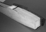 Allow a few minutes for solvent to evaporate. Fit EPP sides and trim
flush with top & bottom of ply box. Do NOT trim in front of nose former.
Here 10mm is left on all four sides to form a cavity for nose weight.
The EPP is best trimmed using a long bladed (X-Acto or similar) knife
using the fuselage sides as a cutting guide. A discarded hacksaw blade
makes an excellent knife if it is ground and sharpened on an oil stone.
Allow a few minutes for solvent to evaporate. Fit EPP sides and trim
flush with top & bottom of ply box. Do NOT trim in front of nose former.
Here 10mm is left on all four sides to form a cavity for nose weight.
The EPP is best trimmed using a long bladed (X-Acto or similar) knife
using the fuselage sides as a cutting guide. A discarded hacksaw blade
makes an excellent knife if it is ground and sharpened on an oil stone.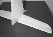 Cut hinges in Fin and Tailplane as shown on the plan. Fit wire elevator
joiner. Using Super-glue fit tri-angular balsa strips to Fin base and
glue to tailplane.
Cut hinges in Fin and Tailplane as shown on the plan. Fit wire elevator
joiner. Using Super-glue fit tri-angular balsa strips to Fin base and
glue to tailplane. - Fit tailplane assembly to fuselage using spray adhesive. Ensure that
it is square. Excess spray adhesive can be removed with white spirit
on a tissue.
- Fit the EPP fuselage bottom as before and trim the EPP again using
fuselage side as a cutting guide.
- Fit EPP fuselage top (Front & Back). Round fuselage corners at base
of Fin before fitting.
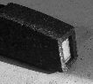 Glue 60 grams or 2 ozs. of lead to front of nose former in cavity formed
by EPP sides. Fit nose block and shape fuselage i.e. round corners using
sharp knife and 180 grade wet & Dry (use dry!).
Glue 60 grams or 2 ozs. of lead to front of nose former in cavity formed
by EPP sides. Fit nose block and shape fuselage i.e. round corners using
sharp knife and 180 grade wet & Dry (use dry!).- Make hatch, shape and cover with CW tape.
- Cover fuselage using CW tape. Overlap each strip by 6 - 10 mm (1/4
to 3/8 inch). In high stress areas such the under the wing leading and
trailing edges apply an extra layer of tape for added strength.
Building
the Wings.
- Lightly sand wing surfaces and remove dust as before. Trim and sand
spar slots to accommodate mainspars. Unfortunately cutting tapered wings
with spar slots result in a tapered spar slot. Remove waste from wing
brace slot.
- Fit top wing spars using Epoxy. Cut to length.
- Fit 3mm bass trailing edges using Epoxy. Use masking tape to hold
in position whilst Epoxy sets.
- With wing upside down fit wing brace and bottom wing spars. Note
trailing edges should form a straight line i.e. not be swept back or
forward. Trim spars to length and shape wing tips.
- Mark position of wing servos (plan drawing is full size. Outboard
position of servo is dependant on servo lead length. Note servo arms
both point outboard of wing.
- Cut rectangular hole for servo in wing ignoring servo mounting lugs.
Note it may be necessary to remove the mounting lugs of the servo.
- Using Hacksaw blade cut slot in EPP for servo lugs and fit servo
so that it is flush with bottom of wing. Note gap between top of servo
and top of wing. From block of EPP removed for servo from wing slice
off the required amount and fit in this void.
 Remove wing servos for covering.
 - Spray wing with spray adhesive and cover wing with GW tape. Start
by laying strip along TE. Then work forward overlapping the previous
strip by 6-10mm. At the leading edge trim tape as you would if covering
in film but overlapping top and bottom by 10mm. Cover top surface of
wing with coloured vinyl tape / lightweight Fablon or iron on film.
This serves two purposes, one to decorate model, the second to reduce
the effects of ultra violet light on the CW tape.
- After covering fit aileron servos. Cut vertical slot in wing to hide
servo leads.
- Cut ailerons to size and shape aileron leading edge. Note the ailerons
are top hinged using Diamond Sellotape (available from Smiths). Cover
the ailerons, starting at TE using either an iron on film or coloured
vinyl tape used to decorate wing.
 Using
scrap wing sleeving manufacture wing fairing, cover and double side
tape in position. Using
scrap wing sleeving manufacture wing fairing, cover and double side
tape in position.- Fit control linkages and adjust to obtain required throws (see flying
section). DO NOT replace the plastic mini-snaplinks with metal devises.
In the event of a mishap the plastic snaplinks will break thereby reducing
the risk of damage to the aileron servos.
Performance
Tweeks
A number
minor of 'modifications' can be made to the Ban-SHE to enhance the model's
performance for competition and sports flying. They are not listed as
standard as most sports flyers would opt for durability and the simple
approach.
- At the expense of durability the Correx tail can be replaced with
4.5mm balsa sheet.
- The aileron hinge gap can be sealed with Mylar strip (draughting
film) and aerodynamic shrouds fitted over the aileron push rods.
- A bolt on wing system can be used instead of rubber bands.
- Appropriate ballast is used whenever the conditions permit but please
remember that if carrying ballast allow a little more airspace to carry
out manoeuvres and avoid over control.
- Couple the flap and elevator so that when turning or looping etc.
the wing can produce the extra lift required more efficiently.
- By far the biggest impact on a model's performance is the pilot!
Practice makes perfect. Fly Ban-SHE in as wide a range of conditions
as possible and as often as possible, with and without ballast.
Flying
- Set the controls to give the following movements for initial flights:
- Ailerons +/- 12 mm
- Elevators +/- 8 mm
- Rudder +/- 25mm
- Flapperons +/- 7mm
- Balance Point 75mm +/- 5mm from LE
- Adjust balance to within recommended limits. Prototypes required
50 - 8ogms of lead in the nose. Check alignment of wing and tailplane
and wing to tailplane incidence (chord lines should be parallel). Laterally
balance wing and check that it is not twisted. If the wing is twisted,
twist back in the required direction and re-smooth covering tape in
position.
- Using wing section template copied from plan set up ailerons so they
follow the wing profile when in neutral. If model is fitted with flapperons
check zero flap is in fact zero flap otherwise performance will be impaired!
Always operate Flaps using a switch or slider where the flaps are going
from one pre-set position to another pre-set position. Operating flaps
without a pre-set neutral is not recommended.
- Depending on the control functions installed will depend the aerobatic
potential of the Ban-SHE. Remember all aerobatic manoeuvres require
energy to perform a manoeuvre. If the model has insufficient speed it
will fall out of the manoeuvre or perform it half-heartedly. Vertical
or near vertical dives are not an efficient way to build up speed, 20-
30 degree dives are much more efficient. Avoid sudden control inputs.
In most cases all they do is scrub off speed and lose height. Try to
fly smoothly with the minimum of control input as not only do the manoeuvres
look better but you will be able to perform more of them before having
to regain height. Try 'stringing' manoeuvres together paying particular
attention to positioning. Be creative and set yourself targets for each
flying session.
- If the lift is good or you are having difficulty penetrating into
wind try ballasting the model. This will increase penetration and help
the model maintain speed through manoeuvres. Note when adding ballast
take care not to disturb the balance point. We have found the optimum
ballast to be 8 ounces (225 grams). Take care when adding ballast as
over-ballasting can lead to tip stalling and a degradation in performance.
- The suggested control settings are a starting point and can be adjusted
to suit your personal tastes. Adjust the balance point so that when
the model is trimmed the elevator is more or less in the neutral position.
An indication that it is about right can be gauged by the amount of
down elevator required to maintain inverted flight. Please remember
if the balance point is moved from the design position it will alter
the elevator neutral position and will necessitate re-rigging the tailplane
to return the elevator to neutral. 6. If you are using a computerised
transmitter program in positive Exponential on the Aileron and Elevator
controls. This will 'soften' the controls around the neutral position
and facilitate smoother flying particularly on the elevator control
when flying inverted or controlling a shallow dive.
- Ban-SHE will take a lot of punishment. It is excellent for building
confidence and will add another dimension to your flying but please
remember if you take a big enough hammer to anything it will break particularly
the lightweight fuselage version.
- The CW tape used for covering degrades in ultra-violet light so store
the model in a relatively cool place away from direct sunlight. Also
do not allow object to rest on the Correx tail surfaces as this will
permanently deform the soft plastic. 8. The Eppler 374 wing section
is very efficient and performs well in light lift so with good ballast
selection Ban-SHE will cope with most wind / lift conditions.
- Finally should you require further assistance or advice please contact
us either by letter, telephone, email or visit our website (http://www.phoenixmp.com)
where you will find useful information on sloping etc.
Happy flying
Stan
Yeo
Ban-SHE 020421
|