|
Peppi
1370mm Crash
Resistant Power Trainer / Sports Aerobatic .20 - .38 cu in. Power Model
Designed
by Stan Yeo
Produced
by PHOENIX MODEL PRODUCTS
Introduction
Peppi is
a crash resistant basic power trainer that will take the budding radio
control model flyer from the first tentative steps up to and including
BMFA 'B' certificate standard. EPP (expanded polypropylene) has revolutionised
learning fly radio control gliders, now it is the time for power flyers
to enjoy the benefits of its quick build time and less stressful flying.
Few EPP models are pleasing to look at or build but they do allow modellers
to enter the hobby in a less painful way. The accessories supplied in
the kit are as used in the prototypes and more than up to the job they
have to do. Likely damage in the event of a serious mishap are a broken
propeller, engine mount and wing dowels so it is worth having spares.
Wing dowel breakage can be avoided if a thicker dowel is used but we prefer
the dowels to break, which are easily replaceable if not glued, rather
than some other part of the structure which would be more difficult to
repair. Items not supplied in the kit include adhesives, radio control
equipment, engine, spray adhesive (used as a pre-treatment before covering)
and coloured vinyl tape (used to protect covering from ultra violet light
and decorate the model). We can supply all of these items at competitive
prices so please ask if you need them.
Tools
/ Materials Required
A limited
range of tools / equipment is required to build Peppi. These include a
Scalpel with a supply of spare blades, 180 grade glasspaper and a soldering
iron. Glues used are Impact Adhesive such as Evo-Stik or Bostik, 12 minute
Epoxy and thin Cynoacrylate (superglue). Impact adhesive is used for all
joints unless otherwise stated. Also recommended is Spray Adhesive for
priming the EPP before covering with the CW tape and coloured vinyl to
decorate the model and protect the CW tape from UV light degradation.
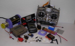
R/C
Equipment
A 4 channel
radio control set with 3/4 servos and rechargeable batteries on 35mHz
is needed to fly Peppi. These start at around £90. Modern electronics
is very reliable so reliability is no longer an issue. We stock and recommend
one of the following as ideal starter sets, Hitec Laser 4, Futaba 6EXA.
Building
the Fuselage
- Lightly sand the fuselage and doublers with 180 grade wet and dry.
Remove dust with a small brush or vacuum cleaner.
- Join fuselage side nose and tail sections using impact adhesive.
Use ply nose doubler to aid alignment.
- Attach ply nose and tail doublers to fuselage side ensuring there
is a left and right side.
- Shorten nose of RIGHT side by 1.5mm to allow for engine right thrust.
- Drill 4.5mm wing dowel and undercarriage dowel holes.
- Mark position of F2 and Superglue 10mm triangular strip to doublers
to reinforce doubler to undercarriage joints and doubler to engine bulkhead
joints.
- Mark and drill 4.5mm dia. holes in engine mount bulkhead for engine
mount.
- Fit engine mount to bulkhead using 4BA screws and 'T' nuts. Tighten
screws to embed 'T' nuts into ply. Cut off excess screw thread to avoid
puncturing fuel tank. Drill hole for throttle control cable (see plan).
Remove engine mount from bulkhead.
- Drill 3mm dia. hole for throttle control rod in former F2. See plan
for position.
- Position fuselage over plan view of fuselage and fit former F2 (use
epoxy) and block B2 (superglue). Position block B1 but do not Superglue.
Ensure fuselage is square.
- Epoxy engine bulkhead and undercarriage mount in position.
- Superglue 6mm sq. strips to either side of SINGLE thickness tailskid
at front.
- Join fuselage at tail, sandwiching tailskid between doublers as per
plan and Superglue.
- Fit EPP fuselage bottom and trim to size using sharp knife. Cut foam
using a slicing action.
- Fit EPP fill-in forward of undercarriage mount.
- Cut hinge in Fin and tailplane by removing one side of Correx flute
along hinge line. Mark centre-line of tail on top surface. Draw a line
either side of the centreline, parallel to it 2mm away from it.
- Using Superglue glue a length of 10mm triangular strip, starting
at the hinge line, to one of the 2mm lines. Cut to length. Lining up
the control surface hinge lines glue the Fin to the triangular strip
just fitted. Fit triangular strip to other side of Fin base.
- Glue tailplane assembly to fuselage ensuring it is square.
- Fit Rudder, Elevator and Throttle servos using Blocks B3,4,&5 as
servo bearers.
- Determine which side of the servo the rudder and elevator control
cables are going to be attached. (Note: changing sides changes direction
of control movement). Draw proposed route on plan in pencil. Mark position
of control cables on block B1 and drill 3mm dia. Holes. Superglue in
position.
- Fit control horns to rudder and elevator as determined above.
- Fit metal control links to cable adapters and fit to control horns.
- Relieve foam fuselage top to accommodate triangular strip at bas
eof fin and masking tape fuselage top in position.
- Determine exit positions of control cables from foam. Make an allowance
for control cable movement (10-12mm between end of conduit and cable
adapter).
- Fit control cables conduits. This is done from the rear by heating
the last 10mm of the straight end of the throttle control rod and burning
a hole through the foam taking care to keep the hole to the size of
the control cable conduit. Practice on waste foam.
- CW tape control cables to inside of fuselage.
- Solder cable adapters to end of control cables. Superglue conduit
to block B1 and cut to length i.e. 10mm beyond B1.
- Centralise servo and attach 'Z' bend rods to servo arm.
- Fit control cables and attach to control horns. Set control surfaces
to neutral and cut control cable to length by marking with felt tip
pen and removing cable for cutting. Allow 25mm between end of conduit
and end of cable. It is easier to cut the cable if the cable in tinned
(soldered) in the area of the cut.
- Refit control cable, reset controls to neutral and cut 'Z' bend rods
to length. Leave 1-2mm gap between end of rod and end of cable for adjustment.
- Clean ends of cable joiner tubes and solder 'Z' rod and control cable
together.
- Un-solder and remove cable adapter from control surface end of control
cable. Whilst solder is still molten wipe cable with a rag or tissue
to remove surplus solder so end of cable can slide into conduit. Remove
servo arm from servo and slide control cable back into cable conduit.
- Fit throttle control conduit.
- Fit fuel tank. Ensure that 'clunk' is just clear of the end of the
tank and free to move.
- Fit top EPP fill-in between engine bulkhead and F2
- Block control cable conduit exits with rolled up paper and spray
fuselage with spray-on adhesive. Leave to dry for 5-10minutes.
- In high stress areas such as the end of the ply nose doubler and
in front of the tailplane apply an extra layer of CW tape before final
covering.
- Cover fuselage with CW tape, overlapping each strip by 10mm and extending
tape to cover engine bulkhead (acts as fuel proofer).
- Cut dowel holes in CW tape.
- Cover fuselage with coloured vinyl tape again covering engine bulkhead.
Cut dowel holes and fit wing / undercarriage dowels.
- Mark position of engine mounting screws on engine mount and drill
5/64in (2mm) dia. pilot holes.
- Fit engine mount and fit engine with 12mm x No. 2 self tapping screws.
- Fit throttle control push rod. It may well be necessary to bend pushrod
at motor end to achieve free movement.
- Remove paper plug in ends of control conduits and refit servo arms
after neutralising servos. Re-solder cable adapters to control cables
ensuring control surfaces are in neutral.
- Assemble undercarriage as per plan and fit undercarriage using elastic
bands.
Building
the Wings.
Rudder
Elevator ONLY Wing
- Lightly sand wing surfaces and remove dust as before. Remove waste
from wing spar slots.
- Laminate the 2 x 1.5mm dihedral braces using Superglue. Mark centreline.
- Superglue dihedral brace to mainspars ensuring first spar is lined
up with centreline and at correct dihedral angle (see plan).
- Fit plastic trailing edge stiffening. Check centre joint is aligned
when wings set at correct dihedral angle. Adjust as necessary.
- Epoxy mainspar to one wing panel. Align top edge with top surface
of wing. Use masking tape to hold wing together whilst epoxy sets.
- Join second wing panel to first, again using epoxy and aligning mainspar
with top surface of wing. Check wing has correct dihedral angle.
- Spray wing with adhesive and allow to dry for 5-10 minutes.
- Cover wing using CW tape and starting at trailing edge as shown on
the plan. Overlap each layer of tape by 10mm. Overlap tape at wing joint
100mm either side of joint.
- To protect the CW tape from ultra violet light and decorate the wing
cover top surface with coloured vinyl adhesive tape or any other opaque,
thin, sticky back plastic of your choice.
Aileron
Wing
- Lightly sand wing surfaces and remove dust.
- Fit hardwood rear spar and cut to length. Hold in position using
masking tape whilst adhesive dried.
- Remove foam from mainspar slot. Mark centre of spar brace and attach
to mainspars. Carry out dummy assembly of wing.
- Epoxy mainspar to one wing panel aligning top of spar with top surface
of wing. Use masking tape to hold wing together whilst epoxy sets.
- Fit second wing panel to spar and join with first wing panel as before.
- Masking tape 12mm balsa sheet centre section TE in position and mark
location of aileron torque rods. Note when assembled there is a gap
of 20-22mm between the torque rods.
- Cut out recesses in trailing edge to accommodate torque rods and
epoxy in position taking care not to let epoxy 'freeze' torque rods
in their tubes.
- Shape trailing edge to follow wing section but keep TE at least 1.5mm
thick at edge.
- Cut out a cardboard rectangle slightly smaller than the base of the
aileron servo. Use this template to cut a rectangular hole behind the
mainspar for the aileron servo. The aileron servo should be a tight
fit in the hole. Check servo fit and then remove.
- Spray wing with adhesive and allow to dry.
- Cover wing with CW tape starting at TE as per instructions shown
on plan. Overlap covering by 100mm either side of wing joint and each
strip by 10mm.
- Using 180grade sanding block bevel nose of ailerons. Lightly sand
top and bottom surfaces and remove loose dust using a vacuum cleaner.
- Hinge ailerons using CW tape. CW tape aileron to torque rod (see
plan). Cover top surface of hinge and CW tape around torque rod with
vinyl tape etc. to prevent UV degradation mentioned previously.
- Cover aileron using self adhesive vinyl tape or the sticky back plastic
covering used earlier.
- Assemble aileron push rods as per plan ensuring control surfaces
are neutral with aileron servo centralised.
Flying
The following
notes are in no way comprehensive but form the basis of an elementary
check-list. It is strongly recommended that you join a local club and
seek their help and guidance. Do not attempt to fly without third party
insurance. The British Model Flyers Association (BMFA) Tel. No. 0116 244028
will be able to provide you with details of your local club and can provide
third party insurance at nominal cost.
Flight
Preparation
- Check all controls operate in the correct sense:
- The Elevator goes down when the control stick is pushed towards
the top of the case.
- The Rudder moves to the right when the control stick is moved
to the right
- The right Aileron goes UP when the control stick is moved to
the right.
- The Throttle is fully open when the throttle stick is pushed
forward towards the top of the case.
- Assemble the model. Check the balance point is 65mm +/- 5mm back
from leading edge (fuel tank empty). Adjust as necessary by adding weight
to the tail or placing weights underneath fuel tank.
- Check flying surfaces for warps (twisting). Warps can be removed
in the wings by twisting the wing in the opposite direction and re-smoothing
the covering using a warm iron.
Flying
- Some common problems
Again these
notes are deliberately brief. It is not possible to cover all aspects
of model flying in the building instructions so if you are inexperienced
please seek help.
- . Model noses over on take-off. Hold in full up elevator until model
starts to lift-off then return elevator to neutral. Bend undercarriage
in to increase propeller ground clearance.
- Model
does not track straight on the ground or is difficult to keep tracking
in a straight line. Possible causes misaligned undercarriage, rudder
control surface out of trim, incorrect sidethrust or model not being
directly into wind for takeoff. Check U/C alignment, neutralise rudder
ensure model is taking off into wind. If problem still persists put
toe-in on undercarriage and or use rates to reduce the sensitivity of
the rudder on take-off but restore full rudder control when airborne.
- Model
wants to climb continuously but when the throttle is closed or the engine
cuts model dives. Not enough downthrust on engine or balance point too
far back. Check balance point and move forward if necessary. Pack up
back of engine with washers and try again. If still insufficient pack
engine mount.
- Model
requires an excessive amount of down trim or up trim. Likely cause fuselage
has been 'bent' during covering resulting in incorrect wing tailplane
incidence angles. Check wing tailplane incidences with plan and adjust
as necessary by recovering the fuselage (remove tape carefully with
hair dryer) taking care not to pre-tension the CW tape.
- Model
'tip' stalls i.e. drops a wing when slowed down. Possible cause a warped
wing, (see above) or trying to fly too slowly.
- When
looping into wind, wings level, the model 'corkscrews' out of the loop.
Most likely cause, other than a warped wing, rudder not trimmed to neutral.
Note direction of screw and adjust rudder trim. Try again ensuring model
is pointing into wind and the wings are level throughout the loop. Repeat
until satisfied.
- Engine
sidethrust needs adjusting if, in a steep climb into wind, the model
drifts to the left (more right thrust) or right (less right thrust)
as the speed drops off.
- Model dives during a roll. Insufficient down elevator during the
'inverted' phase of the roll or lack of speed. Ensure model has sufficient
speed to carry out the roll and start the roll with a slightly nose
up attitude.
- Model dives in a turn. Most likely cause not enough up elevator applied
in the turn. Watch the fuselage during the turn, keep it level.
Finally
should you require further assistance or advice please contact us either
by letter, telephone, email or visit our website (http://www.phoenixmp.com)
where you can find lots useful information and our full catalogue.
Happy flying
Stan
Yeo
Peppi
040502
|