|
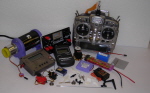
Radio
Controlled Systems |
Back to Article Index
By
Stan Yeo
Often
when talking to modellers it becomes apparent that a surprising
number do not understand the basics of a radio control system, how
it works or what is compatible with what. Whilst I readily accept
that this is not essential to the enjoyment of the hobby a lack
of knowledge can and does restrict the modeller when buying supplementary
airborne equipment. Fortunately though this lack of knowledge means
the modeller errs on the safe side when making these purchases.
The purpose of this article is to explain in simple terms the basics
of our current radio control systems and the meaning of some of
the most common buzz words.
The
System
As
we all know the system comprises of a transmitter which encodes
and transmits the control information. A receiver which receives
the transmitted signal, decodes it and allocates the information
to the respective servos and the servos which move the control surface
(throttle) to the desired position.
1.
The Transmitter
The
main modules to the transmitter (Tx) are the Encoder and the Radio
Frequency module (RF section) which includes a Power Amplifier (PA)
and a 'Mixer'.
The
Encoder
The
Encoder takes the position of each channel control stick or switch
in turn and converts it into 'digital' information. This can be
a pulse of a certain length (time) (PPM) or a binary number (PCM).
It does this approximately 50 times a second (50Hz). So that the
receiver (Rx) knows when one cycle of information is complete and
another cycle starts the Encoder inserts a synchronisation pulse
which 2 to 3 times longer than a normal pulse between each sequence
of pulses (PPM). PCM uses a different system which varies between
manufacturers.
The
RF Section
The
purpose of the RF section is to transmit the encoded information
to the receiver but to do this it must first generate a radio signal
at the correct frequency and mix it with the encoded information
from the Encoder. It must then amplify the signal so it is strong
enough to reach the Rx. Consequently the RF section has three sections,
a Crystal Oscillator to produce a signal at the desired frequency.
A Mixer to mix it with the signal from the Encoder and a PA (Power
Amplifier) to increase the signal strength to the desired level
for transmission.
2.
The Receiver
Like
the transmitter the receiver has a number of sections and is almost
the mirror image of the Tx. There is an RF section sometimes known
as the 'Front End' to receive the incoming signal from the Tx, a
Crystal Oscillator, a Mixer, an IF (Intermediate Frequency) Strip,
a detector and a decoder. The RF section is tuned to receive the
signal from the Tx whilst the Crystal Oscillator (local oscillator)
produces a similar signal but at a lower frequency (455Khz lower),
to be mixed with the incoming Tx signal. The difference in frequency
between the two signals is then passed to the IF Strip. The IF Strip
is a filter which will only allow signals of the IF frequency to
pass through it. With single conversion PPM receivers this frequency
is 455 kHz which is the difference between transmitted signal frequency
and the local oscillator frequency assuming of course that both
are operating on the same channel number! After the IF Strip the
signal is then rectified i.e. converted to a DC signal similar to
that of the Encoder and passed to the Decoder. The Decoders job
is that of a postman's i.e. to post each piece of channel information
to the correct output channel socket for onward dispatch to the
servos. It must do this 100% accurately every time and irrespective
of the number of channels the Tx or Rx has such that an 8 channel
Rx will work with a 4 channel Tx and vice versa etc. It is aided
in this by the synchronisation pulse inserted by the Encoder which
tells the Rx when one chain of information is complete and another
is about to start. The effect of this pulse is to tell the Decoder
counter to stop counting and go back to zero again.
System
Variations
Transmitter
There
are two types of transmitter, one involves pulsing the transmitter
(AM) i.e. switching the output on and off a bit like Morse Code
whilst the other involves 'swinging' the Tx frequency (FM). AM refers
to Amplitude Modulation whilst FM stands for Frequency Modulation.
Most r/c equipment on the 27Mhz band is AM whilst all current 35Mhz
sets are FM. An FM receiver is different from an AM receiver and
neither will work with the others transmitter. AM transmitters are
all PPM (Pulse Proportional Modulation). PCM (Pulse Coded Modulation)
transmitters are generally switchable between PPM and PCM modes.
Receivers
There
are four main types of receiver, AM - PPM for 27Mhz equipment, FM
PPM Single Conversion, FM PPM Dual Conversion and PCM which can
be either single or dual conversion. Needless to say with so many
options and so many different makes there is the inevitable confusion,
most of which seems to centre around the dual and single conversion
PPM system. Most modellers accept that an AM Rx will only work with
an AM Tx, likewise it is accepted that to drive a PCM Rx you need
a PCM transmitter of the SAME make as the receiver. The reason for
this is that with PCM there is not as yet a common encoding standard
as there is with PPM. A bit like the British and American television
standards which are incompatible.
The
main difference between a single conversion receiver and dual conversion
receiver is the dual conversion receiver has two crystals whilst
the single conversion receiver has only one. Theoretically a problem
can arise with a single conversion Rx if there is another transmitter
operating on a frequency which is a harmonic away from the IF frequency
of that receiver. A harmonic of the IF frequency would be 910Khz
(2 x 455) or 227.5Khz (455 / 2). Now 227.5Khz is almost the difference
in frequency between Channel 60 and Channel 83 which we know to
be 230Khz (23 x 10Khz). The same would apply to channels 61 and
84 (either way), 62/85 and 63/86.
In
a dual conversion receiver there are two crystals, the one we change
to change channels and a fixed crystal. The idea is that by reducing
the frequency of the incoming signal down to the IF frequency in
two stages we can increase receiver selectivity and overcome the
theoretical problem associated with single conversion Rxs mentioned
above. The first crystal (the one we plug in) produces a signal
between 24 and 25Mhz whilst second produces a 10.7Mhz signal to
be mixed with the difference of the incoming signal and the first
oscillator signal i.e. 35Mhz - (24-35Mhz). The difference in these
two signals (455 or 470Khz) is then fed to the IF strip as before.
Because Dual Conversion receivers are more complicated than single
conversion receiver they are more expensive. Also as a rule Dual
Conversion Rxs need to be fitted with cyrstals of the same make
as the Rx which is not always the case with single conversion Rxs.
The
Myths
The
main myth is that you can only operate Dual Conversion receivers
from a 'Dual Conversion' Tx and a Rx similar to the one that came
with the set. This is simply not true. There is no difference between
a PPM Tx that came with a Dual Conversion Rx and one that came with
a Single Conversion Rx. Often a retailer will swop a dual conversion
Rx for a single conversion Rx to reduce the total cost of the set.
A point worth checking when you see a set advertised at less than
you would expect it to be!
Another
misapprehension a lot of modellers are under is that different brands
of PPM Rxs will not work with other brands of Tx. In fact there
are a number of receivers on the market that do not have accompanying
transmitters Webra and Jeti are two that come to mind. Likewise
all the leading brands of servos will work with all the leading
brands of R/C equipment providing they have the appropriate leads.
I personally use a JR388 transmitter with mainly Hitec airborne
equipment. With some single conversion Rxs there is even some compatibility
with different makes of crystals i.e. Futaba Hitec and JR. If mixing
and matching I would strongly advise a full range / compatibility
check before flying. Range checks should be carried out in a controlled
manner i.e. a comparison made between a receiver known to be operating
as expected and the new one.
Synthesised
Transmitters and Receivers
In
synthesised radio control equipment the crystal is replaced with
a synthesiser which allows the operator to change to any frequency
in the 35Mhz band without recourse to crystals simply by selecting
a new frequency on the transmitter and then retuning / changing
the crystal in the receiver to the new frequency. If the receiver
is synthesised the normal procedure is to switch on the transmitter
close to the receiver. Switch on the receiver and activate channel
scanning. The receiver will then lock on to the strongest signal
which should be the parent transmitter. After tuning the Rx will
stay on the new frequency until retuned to a new one. A synthesised
Tx can used with a crystal Rx and vice versa. A synthesised module
in the Tx or Rx is completely independant of the other. Using a
synthesised transmitter does place a greater responsibilty on the
operator to ensure that they know the channel number they are operating
on. There are some Txs that can be fitted with a channel checker
that prevents the Tx being switched on if there is another transmitter
transmitting on that frequency. A few transmitters have a double
switch on procedure i.e. on first switching on the Tx displays the
transmitting frequency but does not start transmitting until a second
switch is activated.
Summary
I hope
this article has been of value and more importantly easy to understand.
I have kept the explanations as simple as possible as we do not
need to know how it works just the basic concepts so we can make
informed decisions when buying new equipment.
|
Back to top
|