|
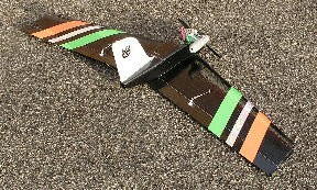
Crazee-BAT
1170mm Crash
Resistant Sports Aerobatic Power Model for 0.20 - 0.32 cu in. Engines
Designed
by Stan Yeo
Produced
by PHOENIX MODEL PRODUCTS
Introduction
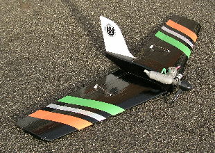
The Crazee-BAT
is an EPP (expanded polypropylene) model designed to put the wow back
into sport flying without some of the risks associated with this type
of model and flying. EPP models have a reputation for being very tough
and the Crazee-BAT is no exception. It will survive all but the most severe
crashes with only a broken propeller and if unlucky a broken engine mount.
Crazee-BAT is quick with responsive controls and good low speed handling
characteristics. It will perform all manoeuvres expected of a flying wing
including loops, rolls, and inverted etc. Although the finished model
is unlikely to be as aesthetically pleasing as its wooden counterparts
this is more than compensated for in the short build time and durability.
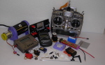
The accessories supplied in the kit are as used in the prototypes and
more than up to the job they have to do. Items not supplied in the kit
include the adhesives (2 part Epoxy, thin Superglue and Spray Impact Adhesive).
Radio
control equipment (2 standard servos 4ch Rx and a square Rx battery),
the engine (SC25/32 or MDS28 etc.), Sellotape Diamond for the Elevon hinge
and coloured vinyl tape (used to protect covering from ultra violet light
and decorate the model). We can supply all of these items at competitive
prices so please ask if you need them.
Tools
/ Materials Required
A limited
range of tools / equipment is required to build Crazee-BAT. These include
a Scalpel with a supply of spare blades, a sharp long bladed knife, 180
grade Wet & Dry abrasive paper, a soldering iron and a drill with a selection
drill bits. The long bladed knife can be made from a broken piece of hacksaw
blade about 75mm long, sharpened on a grindstone (take care not to overheat
the blade when grinding the teeth off as this will destroy the hardness
of the steel) and honed on a whetstone or oilstone. This blade is better
than commercial ones as due to its flexibility. It is very useful when
trimming the EPP attached to the fuselage sides.
R/C
Equipment
A 4 channel
radio control set on 35mHz, with rechargeable batteries. 2 standard servos
and 1 mini servo. If the transmitter does not have Elevon mixing then
an airborne mixer is required. The receiver battery should be of the 'square'
type rather than the 'flat' type normally supplied with the set. If you
do not have a transmitter with built in control mixing then it may be
more cost effective to buy a new TX rather than buy a mixer. The Futaba
6EXA comes highly recommended as it not only has the necessary control
mixers but has a 6 model memory and other facilities which are very useful
in setting up the Crazee-BAT.
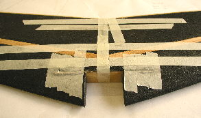
Building
the Wing
- The wing
is built upside down so that the reduction in thickness towards the
tips results in a small amount of dihedral rather than anhedral.
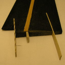
- Using
a sharp scalpel and a 600mm straight edge widen the mainspar slots to
accommodate the spars. This is necessary because the computer controlled
hot wire cutter cannot cut parallel slots when cutting a tapered wing.
- Using
2 part Epoxy (12 minute recommended) fit the top mainspars. Note these
are 5mm thick. Weight down on a flat surface whilst epoxy sets.
- Again
using epoxy fit the spruce rear spars. Use masking tape to hold spars
in place whilst epoxy sets.
- Using
Superglue to laminate the 2 pieces of 1.5mm ply that make up the front
and rear wing spar braces (hold items together and run superglue along
edges).
- Join
wing using epoxy and fit front and rear spar braces.
- Angle
ends of bottom mainspars to match wing root and fit. Note bottom spars
are 3mm thick.
- Shape
wing tips.
- Bevel
the front of the elevons as per plan to accommodate down elevon. Cut
elevons to length and shape.
- Lay wing
on flat surface the correct way up. Position a wing servo just behind
the mainspar at right angles to the rear spar. Route the servo lead
as per the plan and adjust servo position so that there is sufficient
free lead to plug into the receiver. Mark position of servo.
- Centre
both the Elevon servos using the Tx before fitting. After centreing
rotate the arm one spline to the rear to counteract Elevon differential
movement due to the top hinging of the Elevons.
- Make
a rectangular cutting template, allowing for the output arm and marginally
smaller than the servo. The servo needs to be a tight fit in the wing.
Use the template to cut a rectangular hole through the wing.
- Cut slots
for the servo lugs and servo lead. Push servo into wing so it is flush
with the top surface.
- Turn
the wing over and fill the gap between the servo and the bottom of the
wing with an offcut from the rectangular block removed from the wing.
- Repeat
procedure for second wing servo.
- Cut slot
1mm wide and 3mm deep, routed as per plan, to house servo lead. Bury
servo lead in wing.Lightly sand the wing and fill in any gaps around
the mainspars. Any filler can be used including epoxy loaded with micro
balloons or Polyfilla.
- Fit fuselage
to wing and mark fuselage position on wing and wing position on fuselage
at nose. Remove fuselage from wing.
- Lightly
spray wing with impact adhesive and cover the wing following the sequence
indicated on the plan i.e. start at the rear spar and work forward overlapping
each strip by 5-10mm. On the top surface of the wing DO NOT cover the
previously marked fuselage area except for the first 2-3mm. Where the
CW Tape goes around a compound curve the wrinkles can be reduced using
a film covering iron at a suitable temperature. This will not harm the
EPP providing the iron is not allowed to dwell in one spot too long.
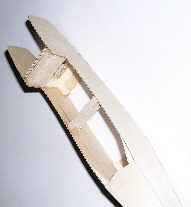
Building
the Fuselage
- Lightly sand fuselage sides with 180 grade Wet & Dry (use dry) to
remove any traces of ply release agent.
- Using plan and downthrust distance piece mark position of engine
bulkhead on fuselage sides.
- Drill holes for engine mount in engine bulkhead. Please note the
mount is offset to allow for engine sidethrust (see plan). Mark the
engine bulkhead front and back and fit the 4BA pronged 'T' nuts to back
of bulkhead.
- Fit 6mm triangular strip to fuselage sides using Superglue ensuring
there is a Left and Right hand side!
- Superglue balsa downthrust block and fuel tank distance piece in
place ensuring that the fuselage is square (use a fitters square / set
square).
- Superglue engine bulkhead in place then join fuselage at the rear
ensuring that fuselage is straight.
- Fit 1.5mm ply fuselage top, front and rear. To encourage the ply
to bend to the curvature of the fuselage sides wet the top surface.
- Using rubber bands locate the ply fuselage bottom. Fit fuselage to
wing and mark length of fuselage bottom. Cut fuselage bottom to length
and glue in position.
- Trim excess ply from top and bottom sheeting.
- Superglue 8mm triangular strip to base of Fin. Mark centre of fuselage
at front and back of Fin and fit Fin ensuring that it is
 vertical.
If after gluing Fin is not vertical then slice triangular strip on inside
of bend and pack out with thin card and Superglue in place. vertical.
If after gluing Fin is not vertical then slice triangular strip on inside
of bend and pack out with thin card and Superglue in place.
- Fuelproof the engine compartment and front of fuel tank bay with
thin Superglue. Do this outside or in a well ventilated area as the
fumes carry a hazard warning. Alternatively use varnish or a proprietary
fuelproofer.
- Using spray impact adhesive fit EPP sheet to one side of the fuselage.
Spray both surfaces and allow a few seconds for solvent to evaporate
before making the joint. Do not worry about getting impact adhesive
on the Correx fin as it can be easily removed using white spirit. Using
a long bladed sharp knife trim the off the excess EPP. Keep the cutting
angle as low as possible to avoid tearing the foam. As mentioned previously
the best tool for this task is the sharpened hacksaw blade described
in the Tools / Materials section. Lubricate the knife with white spirit.
- Fit EPP to other side of fuselage and trim to shape as before.
- Fit EPP to base of fin. Note EPP will have to be relieved to accommodate
triangular strip at base of fin. Fill in gap at front of fin with scrap
EPP.
- Fit EPP to front of hatch and bottom of fuselage at rear (this piece
is slightly thicker than sides and top).
- Manufacture hatch. Use spare ply to for hatch locating tongue.Cover
Fuselage. Lightly sand and fill any gaps as before.
- Check fuselage fit to wing and adjust as necessary.
- Spray fuselage with impact adhesive and cover fuselage with CW Tape
starting with the sides. Do not cover the fuselage where it is overlapped
by the wing except for the first 2-3mm. Use iron as before to remove
any wrinkles.
- Fit fuselage to wing using 2 part epoxy. Using short 25mm wide strips
of CW Tape seal wing to fuselage joint.
- Cover the model with either coloured vinyl tape (recommended) or
an heatshrink film to decorate the model and protect the base covering
(CW Tape) from the effects of ultra violet light, including the inside
of the engine bay. If using coloured vinyl tape use iron as before to
shrink tape around compound curves.
- It is recommended that the ailerons are covered in a heat shrink
film such as Easycoat in ONE piece (seam on inside of hinge i.e. elevon
leading edge). This avoids having exposed edges that can peel back.
- Hinge the elevons using Sellotape Diamond as per plan.
- Drills holes for control horns. After drilling reiforce hole with
runny superglue.
- Before fitting the Elevon servos centre the servo / output arm. After
centreing rotate the arm one spline to the rear to counteract Elevon
differential movement due to the top hinging of the Elevons.
- Connect up elevon controls.
- Install fuel tank with fuel tubing and fit engine.
- Fit throttle servo and throttle pushrod. Adjust length for correct
operation throttle. Install remainder of radio equipment.
Flight
Preparation
With the
controls and balance point correctly setup the Crazee-BAT is both easy
to launch and a dream to fly but if insufficient care has been taken during
the setting up process then beware! Below are a few notes on preparing
the model for flying.
Control Movements:
- Ailerons: +/- 13mm
- Elevator: +/- 11mm
- Balance Point: 60mm - 65mm (from front of engine bulkhead)
- Check flying surfaces for warps (twisting). Warps can be removed
in the wings by twisting the wing in the opposite direction and re-smoothing
the covering using a warm iron.
- Check the balance point is 60 - 65mm back from the front of the engine
bulkhead. Adjust as necessary by adding weight to the tail or screwing
weights to the front of the engine bulkhead beneath the engine mount
tank. Tape hexagonal pencil to balance point in centre of wing to assist
in balancing the model.
- It is most important that the controls the controls are working symmetrically
i.e. full up or down elevator movements are equal and likewise for the
ailerons. Asymmetric movement of the elevator will result in 'corkscrew'
loops.
- Use the template on the plan to set the reflex (up elevator) on the
elevons for neutral elevator.
- Check you have the specified downthrust and RIGHT sidethrust. The
right thrust is extremely important. If it is wrong then the model will
veer off violently to the left or right when launched due to lack of
flying speed.
- Fit the propeller in the 10 - 4 clock position so that when the engine
cuts it will come to rest in the horizontal position and not shed a
blade on landing.
- Before flying do a full range check of the radio equipment. This
should be a comparison check against a model where the equipment is
known to be working satisfactorily.
- If the engine is new run a couple of tanks of fuel through it before
attempting to fly. Run the engine slightly rich in the beginning and
do not attempt to adjust the slow running needle valve until the engine
is run in. We would also advise that the idle RPM is set slightly higher
again until the engine is run in. We would also suggest the model is
flown at a safe height should the engine cut prematurely.
- Always allow the engine to reach its operating temperature by running
at full throttle for a few seconds before launching the model.
- Charge the batteries!
Flying
The following
notes are not designed to be comprehensive as pilots of the Crazee-BAT
should be relatively experienced. Due to noise and other problems etc.
that the hobby is experiencing please think of others when you are flying.
It is strongly recommended that you do not attempt to fly without third
party insurance. The British Model Flying Association (BMFA) Tel. No.
0116 244028 will be able to provide you with third party insurance at
nominal cost and also give you details of your local club.
- If the above procedures have been completed successfully then the
model should fly straight of the board as they say with the minimum
of trimming.
- Check all controls operate in the correct sense i.e. the Elevator
goes down when the control stick is pushed towards the top of the case,
the right Aileron goes UP when the control stick is moved to the right
and the engine shuts own when the throttle stick is pulled towards the
bottom of the TX case.
- Crazee-BAT is launched underarm at full throttle, in a slightly nose-up
attitude with a small amount of up-trim to counteract the 'dip' after
launching due to lack of flying speed. Once flying speed has been achieved
then the trim can be returned to neutral.
- Adjust aileron and elevator trims as required until the model will
fly hands off in a shallow climb at full throttle.
- To check for correct sidethrust carry out a fast low pass, into wind
and put Crazee-BAT into steep climb. It the model veers to the left
or right as the flying speed drops off this would indicate the sidethrust
needs adjusting.
- On going quickly to full throttle from idle the model will 'dip'
slightly until it reaches full flying speed.
- Model dives in a turn. Most likely cause not enough up elevator applied
in the turn.
- When flying inverted the model will require a small amount of down
elevator. If it requires an excessive amount this could indicate the
balance point is too far forward, if very little then it could be either
too far back or too much downthrust. A 'twitchy' elevator or a tendency
to spin would indicate the balance point is too far back.
- When flying inverted be aware that when turning, particularly when
close to the ground, that some elevator movement is lost with the input
of aileron control. It is not a problem when the model is the correct
way up due to the type of wing section used.
- Carry out a series of loops into wind. If the model screws out of
the loop consistently in one direction this could indicate asymmetric
elevator movement. Check elevator throws.
- When the engine cuts there should be a negligible trim change from
power on to a shallow but moderately fast glide.
- If after a bit of a thump on the nose the engine starts to
play up then it is a possible that the clunk is tucked
under the tubes at the front of the tank. Take the hatch off and check.
Finally should
you require further assistance or advice please contact us either by letter,
telephone, email or visit our website (http://www.phoenixmp.com) where
you can find lots useful information and our full catalogue.
Happy flying
Stan
Yeo
Crazee-BAT
040215
|