|
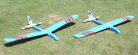
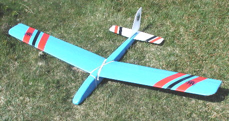
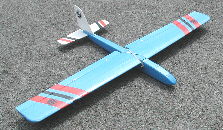
Synergy
DUET
1570mm EPP
Crash Resistant Trainer / Sports Aerobatic Slope Soarer
Designed
by Stan Yeo
Produced
by PHOENIX MODEL PRODUCTS
Introduction
The Synergy
Duet is available in two versions. One as a rudder elevator basic trainer
(R/E Trainer), the other as an aileron trainer/sports aerobatic model,
(Duet Sport), capable of most acrobatic manoeuvres when fitted with flapperons
and coupled flap elevator. Aileron wing conversion kits are available
to upgrade from the R/E trainer. Building time should be about ¼ to 1/3
that of an equivalent wood and foam construction model, i.e. 15 - 20 hours.
Before starting please read these instructions in conjunction with the
full size plan and familiarise yourself with the parts. If you do require
assistance please do not hesitate to contact us.
Tools
/ Materials Required
The glues
required are thin Superglue, (used for wood joints), 2 part epoxy (12
minute recommended) used for wing spars and braces. Spray impact adhesive,
used to glue EPP and prime foam prior to covering. Also required is an
external covering to go over the top of the base covering material, which
is cross weave filament tape (CW Tape) to decorate the model and stop
the ultra violet light damaging the CW tape. This can be a coloured vinyl
sticky back tape (recommended) or an iron film. Tools required consist
of a soldering iron and multi-core solder, a modelling knife, sanding
block and a pair of pliers. A long (75mm) bladed knife made from a hacksaw
blade is also very useful. 10mm thick Sundela board is recommended for
use as a building board, small fitters square or set square, lead sheet,
masking tape, cling film plus a selection of long elastic bands.
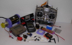
R/C
Equipment
The R/E Trainer requires 2 standard size servos, square receiver (Rx)
battery pack, (not the flat one supplied with most R/C outfits), a 4 channel
Rx and switch harness. In addition the Duet Sport requires an 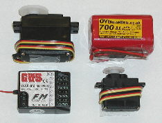 aileron
servo(s), plus extension lead(s). For single aileron servo operation a
standard servo can be used but it is strongly recommended that a twin
aileron servo assembly is fitted even if you do not own a computerised
transmitter (Tx). For a twin servo operation please fit metal geared micro
servos as opposed to plastic geared servos. The additional cost is soon
recovered after the first hard landing when in all probability the plastic
gears will get broken. aileron
servo(s), plus extension lead(s). For single aileron servo operation a
standard servo can be used but it is strongly recommended that a twin
aileron servo assembly is fitted even if you do not own a computerised
transmitter (Tx). For a twin servo operation please fit metal geared micro
servos as opposed to plastic geared servos. The additional cost is soon
recovered after the first hard landing when in all probability the plastic
gears will get broken.
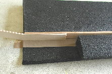
Building
the Fuselage
- Lightly sand ply fuselage side to remove splinters and release agent.
- Drill
wing dowel holes in ply sides. If building trainer version drill both
sets of rear dowel holes ready for conversion to aileron wing. Ensure
a tight fit.
- Fit balsa
strip longerons to ply sides using Superglue leaving gaps for balsa
blocks. Check there is a left and right side !!
- Cover
plan with cling film and position fuselage sides above plan view of
fuselage, using wing dowels to assist with alignment. Position balsa
blocks. In conjunction with wing dowels use rubber
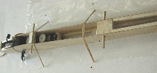 bands stretched over top of fuselage to position sides correctly. Use
set square for final vertical alignment.
bands stretched over top of fuselage to position sides correctly. Use
set square for final vertical alignment.
- Fit balsa
block at front and rear of wing, plus block at fuselage bottom under
wing trailing edge (TE). DO NOT GLUE DOWELS, they may need replacing
after an arrival!
- Fit nose
former and join fuselage at tail. Fit ply tail seat.
- Fit ply
fuselage bottom forward of wing TE and ply top at nose, forward of hatch.
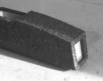
- Spray
with impact adhesive, one side of fuselage and one EPP foam side and
allow a couple of minutes for solvent to evaporate. Fit foam side to
fuselage ensuring that the 'spare' is at the nose end (required to form
cavity for nose weight).
- Using
sharp long bladed knife trim EPP foam ensuring that it is cut square
to fuselage top and bottom.
- Fit other
EPP fuselage side and trim as before.
- Decide
which side of the servo the control rods need to be connected for the
controls to operate in correct sense. Remember control exit is on opposite
side. Insert piano wire push rod into control outer and fit elevator
control rod checking that pushrod moves freely. Anchor to fuselage sides
in between wing TE and tailplane using balsa strip off-cuts or CW tape.
- Fit fuselage
bottom again ensuring any surplus is at nose end.
- Fit EPP
to nose top forward of hatch aligning with ends of EPP sides.
- Cut sheet
lead into 3 or 4, 30 mm sq. blocks and glue to front of nose former
inside EPP foam cavity.
- Fit noseblock
and trim any surplus.
- Remove
1.5mm strip of plastic from Correx Tailplane and Fin along hinge line
to form hinge (as shown on plan).
- Fit,
(using superglue) 10 mm triangular strip to base of Fin to line up with
tailplane as shown on plan. Check using set square that fin is square
when resting on base. Adjust as necessary.
- Mark
tailplane centre on Correx and glue Fin in position using Superglue
ensuring it is square with the Tailplane. TIP If fin is not
 vertical after gluing to tailplane, cut balsa strip along its length
on inside of lean and insert sliver of thin card to correct lean. When
satisfied fix with Superglue.
vertical after gluing to tailplane, cut balsa strip along its length
on inside of lean and insert sliver of thin card to correct lean. When
satisfied fix with Superglue.
- Cut fuselage
top to shape above tailplane seat and relieve inside of fin slot to
accommodate 10 mm triangular strip at Fin base.
- Epoxy
Tailplane to Fuselage ensuring that it is both square and in line with
the axis of the fuselage i.e. Fin has not got built in left or right
rudder.
- Position
fuselage top hot wire 'drill' hole for Rudder control rod (use non -
Z bend end of push rod). Only heat the last 10 mm. Drill a test hole
in scrap EPP - you will be surprised at how easy the foam melts!
- Fit rudder
control rod and check for freedom of movement as before.
- Fit fuselage
top. Trim to size as before and radius all corners using a sharp knife
and 'carving' action before final finishing with 180 grade wet & dry.
- Manufacture
hatch.
Building
the Wings.
Rudder
Elevator Wing
- Laminate ply wing braces by holding them together and running Superglue
along the edges.
- Using 2 part Epoxy build up wing spar assembly and mark centre line.
- Using spray impact adhesive, glue TE reinforcing to wing TE. Take
care. This is a one shot operation that can go wrong!
- Epoxy one wing leading edge section to main spar. When set epoxy
trailing edge section in place. Use masking tape to hold sections in
place while epoxy sets.
- Repeat the above for other half of the wing ensuring in all cases
the wing sections are properly seated on main spar and aligned with
it.
- Shape tips, check main spar is flush with foam and adjust as necessary.
Aileron
Wing
- Using epoxy assemble main spar on flat surface as per plan and mark
centre line and spar top (determined by dihedral as a result of spar
tapes)
- Epoxy rear spars to wing TE sections using masking tape to hold in
place.
- Epoxy one half of wing to main spar. Use a combination of masking
tape and not too tight rubber bands to hold EPP in place whilst epoxy
sets. Take great care to ensure that wing is properly seated against
main spar and equally positioned along it top and bottom. Smooth / remove
any surplus epoxy.
- Fit TE spar brace. Note this will not be a perfect fit due to wing
taper.
- Cut out recesses in wing for aileron servo(s). All servos are fitted
 behind
main spar. For twin aileron servo installation, lay wing upside down
on flat surface. Position servo behind main spar, stretch servo lead
in towards wing joint. Position servo so that the end of the lead extends
30 mm beyond wing join and cut 'snug' rectangular section out of wing
to accommodate servo. A long bladed scalpel is required for this operation.
Cut small slots for servo plugs and servo lead. Position servo in wing.
Turn wing right way up and slice top off 'rectangular' block to fill
cavity above the servo. Remove servo and glue insert in position. Repeat
for second servo. behind
main spar. For twin aileron servo installation, lay wing upside down
on flat surface. Position servo behind main spar, stretch servo lead
in towards wing joint. Position servo so that the end of the lead extends
30 mm beyond wing join and cut 'snug' rectangular section out of wing
to accommodate servo. A long bladed scalpel is required for this operation.
Cut small slots for servo plugs and servo lead. Position servo in wing.
Turn wing right way up and slice top off 'rectangular' block to fill
cavity above the servo. Remove servo and glue insert in position. Repeat
for second servo.
- Shape leading edge of ailerons according to wing servo installation
(see plan).
- Check length of ailerons, adjust as necessary. Shape tips (ailerons
& wing)
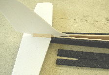
Covering
Wing
- Before starting covering remove any dust that has collected in the
foam pores with a vacuum cleaner.
- Lightly spray (nozzle 60mm from work) the wing with impact adhesive
and allow a couple of minutes for the solvent to evaporate.
- Lay a strip of CW tape along edge of trailing edge such that the
overlap is equally spaced between top and bottom surface. Allow tape
to overlap wing joint each side by 50 - 60 mm.
- Apply the next layer of tape on underside, of one wing panel, again
overlapping the wing joint by 50 - 60 mm. Allow for wing taper by overlapping
first strip at root by 5 mm and abutting rear spar at tip. Note for
non-aileron wing overlap at tip will be 12 mm. Repeat for opposite wing
panel.
- Repeat Step 4 for top surface of wing.
- Repeat Steps 4 & 5 until wing is covered. Where there is loose tape
around compound curves slice tape to allow it to overlap. The technique
for leading edge is similar to that of fuselage corners, i.e. hold tape
at right angles to wing surface and run long bladed knife along tape
using opposite surface as a cutting guide. Lubricate knife blade with
White Spirit.
Fuselage
- Check fit of wing to fuselage and wing alignment with tailplane. Adjust
as necessary.
- Remove control push rock if fitted and block ends of tubes to prevent
ingress of spray adhesive.
- Spray fuselage with impact adhesive. Allow 2 or 3 minutes for solvent
to evaporate.
- Start taping fuselage by laying first strip of CW tape full length
of fuselage in line with underside of tailplane. Repeat for opposite
side. Lay second strip alongside with an overlap of 8 - 10 mm. Trim,
using long bladed knife lubricated with white spirit, by using fuselage
bottom as a guide for the knife blade and using free hand to keep tension
on tape whilst cutting. It may be necessary to place weight on fuselage
during this operation to stop it moving whilst trimming the CW tape.
- Repeat
above until fuselage is covered. Treat the Fin / Tailplane joint as
a separate item.
Final
Covering
It is recommended
that the top surface of the wing and the fuselage is covered in an opaque
material such as a coloured vinyl sticky back tape or iron on heat shrink
film such as Profilm or Easycoat. There are two reasons for this, one
to protect the base covering (CW tape) from the effects of Ultra Violet
light, the other simply for decoration. For this type of model we recommend
the vinyl tape as it is cheaper and is considerably quicker and easier
to apply. Remember a sports model's flying takes priority over looks.
Even so a more than creditable finish can be achieved with the coloured
vinyl tape.Repeat above until fuselage is covered. Treat the Fin / Tailplane
joint as a separate item.
If covering
with coloured vinyl tape, use a similar procedure to that of the CW tape.
On the rudder elevator wing, to prevent the tape lifting at the trailing
edge, overlap with Sellotape Diamond. Sellotape Diamond is also used to
seal the leading edge of the tailplane and fin to reduce drag. The coloured
vinyl tape we supply can be shrunk slightly with a cool iron if required
to remove small wrinkles. After covering fit wing dowels (use bent piece
of wire inserted in dowel holes from inside of fuselage to determine external
position) DO NOT GLUE DOWELS. Hinge ailerons using Sellotape Diamond.
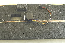
Equipment
Installation
Rudder
Elevator Controls
After covering
installation of the radio equipment can be carried out.
- Assemble Rudder & Elevator servos onto their balsa blocks. Do not
glue into place yet. Please note it will be necessary to offset the
rudder servo to allow use of a longer servo arm to achieve the required
rudder movement.
- Fit Rx battery in nose along with Rx and switch harness. Position
rudder and elevator servos in fuselage ensuring they do not foul wing
dowels or aileron servo (single servo installation).
- Check position of balance point. Adjust as necessary. This may require
repositioning of rudder elevator servos.
- When satisfied dribble Superglue down sides of servo mounting blocks
to secure. Use offcuts of 6 or 10 mm triangular strip at corners of
front and back of servo mounting blocks to provide added support.
- Remove servo arms from rudder & elevator servos. Zero trims on Tx.
Switch on R/C equipment and zero servos.
- Fit piano wire pushrods to servo arms (pushrod underneath servo arm)
and install pushrod/servo arm ensuring arm is as near to neutral as
possible. If using computerised Tx use Sub.Trim menu for final adjustment.
- Fit control horns and assemble snaplinks to threaded adapters. Check
depth of hole in threaded adaptor. With control surfaces in neutral
mark end of adapters on pushrods and allowing for depth of hole in adapter
cut pushrod to length.
- Remove snaplink assemble and using a pair of pliers, spring loaded
with a rubber band, tin the inside of threaded adapter hole. Do not
spend too long on this operation as you will melt snaplink!
- Replace snaplinks on control horn and with control surface in neutral
solder in place.
- Check controls for correct sense and range of movement. This may
entail connections the rudder pushroad to outer hole on servo arm and
inner hole on control horn to get maximum movement. It will probably
be the reverse for the elevators as less angular movement is required.
Aileron
Controls
Single
Aileron Servo
- Cut away CW tape and install aileron servo.
- Connect up to Rx and centre aileron trim and servo output arm.
- Masking tape a pencil or similar straight edge to underside of wing
for use in setting ailerons in neutral position (bottom of aileron should
be parallel to straight edge.
- Manufacture aileron pushrods as per plan and fit. Adjust nylon clevis
as necessary to achieve neutral (see above)
Twin Aileron
Servo
- Cut away CW tape and install aileron servos.
- Cut slit along wing, each side, 1 mm wide, 3 mm deep to accommodate
servo leads. Bury servo leads in wing and cover slit with length of
25 mm wide CW tape.
- If using non-computerised transmitter (Tx) plug Y lead into aileron
channel in Rx and connect servos. Check ailerons are operating in correct
sense i.e. on application of Left aileron the left aileron moves UP.
Use servo reversing to correct if necessary.
- If using a computerised transmitter (Tx) plug aileron servo extension
leads into the aileron and flap channels on the Rx and connect servos.
Set transmitter up in Wing Flapperon mode and using Sub-Trim menu to
align aileron servo output arms (look along underside of wing). Check
for correct sense and adjust if necessary using Servo Reversing facility.
If no matter what you do one function is always operating in the wrong
sense swap the channels the servos are plugged into. This should cure
the problem.
- When satisfied servos are set up correctly CW tape in position.
- Masking tape a pencil or similar straight edge to underside of wing
 for use in setting ailerons in neutral position (bottom of aileron should
be parallel to straight edge.
for use in setting ailerons in neutral position (bottom of aileron should
be parallel to straight edge.
- Manufacture aileron pushrods as per plan and fit. Adjust nylon clevis
as necessary to achieve neutral (see above)
Flying
- Having set controls and balance as per instructions then the model
is ready to fly, but before attempting to fly, give the radio equipment
a full overnight charge.
- If a newcomer to model flying/slope soaring, we strongly recommend
you join the local slope soaring club and take out third party insurance
either through the British Model Flying Association (BMFA) Tel No. 0116
2440028
- Again, if a newcomer to this form of flying we recommend you enlist
the help of a 'slope' experienced flyer to carry out initial flights
and final 'trimming' of the model.
- Please check out our website www.phoenixmp.com. There you will find
a number of useful articles on various aspects of model flying. They
are well worth reading before and after a flying session.
Happy Landings
Stan Yeo
|